CSAG Variable Speed Drive Types
March 26, 2010CSAG Multiple Drives – Coordinated Control
March 26, 2010
Control Systems Application Guide |
Previous “Variable Speed Drive Types” • Back To Index • Next “Multiple Drives – Coordinated Control”
Motor Control Basics: Drive Operating Modes
Understanding a motor’s operating modes is crucial in selecting and using it for your application. If you know the various DC motor torque control methods, for instance, you can set parameters for optimized performance. Control of motor torque and velocity or speed are operating mode selections available to most basic DC drives and to some flux vector type AC drives. With some products, Velocity mode operation can include capacity for regeneration.
Let’s take a look at torque control motor operation for DC and AC drives, their effects on velocity and how you can operate them in the most effective manner.
DC Drives: DC Motor Torque Control:
To control a DC motor’s torque, a DC drive will regulate the armature current, which is the total amperage that moves through a system with a specified voltage, resistance and electromotive force (EMF).

The armature voltage is unregulated, allowing the motor to operate at whatever speed is necessary to achieve the set current/torque level. Such a setup may be used for any constant torque drive rolls and simple winders to adjust approximate tension for small build ratio centerwind operation. For torque mode center winders and a fixed input reference, torque remains constant, giving a taper tension effect unless the machine operator increases the torque set-point as diameter increases.
Straight torque control of a DC motor can have the undesirable effect of causing run-up to maximum speed in the event of web breakage or load loss unless the drive includes a “max speed or voltage limiting” function. You can compensate for these effects with optional drive add-on boards and/or external DC motor torque control circuits to provide full-featured constant tension center wind (CTCW) control with included compensation for friction, inertia, diameter change and more. Some drives, such as the Carotron ELITE PRO digital DC drive, include CTCW firmware.
Some products that offer exceptional torque control for DC motors include:
- TROOPER® Series: The TROOPER® Series of DC motor controls offers affordable speed and torque control for 1/8-3HP motors.
- ADP100® Series: The Adaptable Drive Package ADP100® Series has a comprehensive range of controls for 1/4-5HP DC motors.
- BLAZER® Series: In the BLAZER® Series, you’ll find performance-built controls for 1/4-5HP isolated DC motors.
- ELITE® Series: For control over 5-300HP DC motors, there’s the ELITE® Series of motor controls.
- CHOICE® Series: The CHOICE® Series is a non-regenerative DC motor controller with a full range of speed and torque control for 5-150HP motors.
- ELITE® PRO Series: The ELITE® PRO Series includes reliable, rugged drives suitable for demanding applications.
- RCP200 Series: With the RCP200 Series, you’ll get flexibility and more control in 1/4-5HP motors.
AC Drives Torque Control:
An AC drive uses complex processing of motor voltage, current, frequency and rotational position to impart torque regulation capability. Torque mode operation usually requires encoder feedback. Even evaluating an inverter drive’s torque regulation ability is not straightforward. Do not assume that an inverter and motor operating in “torque” mode will produce a linear and proportional output torque when compared to the reference. Complete DC motor torque control may be dependent on the use of an external torque reference circuit or control that has flexibility and adjustability to compensate for any drive/motor shortcomings.
DC Drives: Speed and Torque Control of DC Motor (Velocity Control):
The drive will normally control the armature voltage to regulate DC motor speed. How well it does this depends on what feedback signal is used to represent the motor speed. Refer to the Section C, “Open Loop and Closed Loop Control.” Common selections for some DC drives are as follows:
- AFB – Armature feedback
- TFB – Tachometer feedback
- EFB – Encoder feedback
1. AFB — Armature Feedback
The armature voltage feedback method, also called armature feedback, relies on the ability of a DC motor to act as a DC generator. When a DC motor is rotated, it will generate a voltage level called counter or back EMF that is proportional to the speed of rotation. As on all “generators,” the generated output is also affected by the strength of the field magnetic flux.
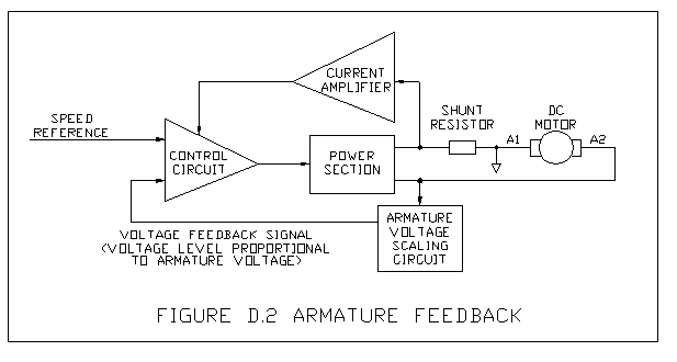
Since the armature voltage coming from the drive is output in the form of pulses, the counter-EMF voltage can be measured in between the pulses. This signal is then introduced to the speed regulation circuit of the drive, the velocity loop, to adjust the drive power section to maintain a constant motor voltage. The primary benefit of armature feedback with Carotron DC drives is that no additional drive or motor components are required to achieve motor torque control.
Some problems associated with armature feedback operation are related to certain DC motor characteristics. One problem is, even with constant armature voltage, the motor speed may drop several percent when the motor is loaded. This drop is due to “internal resistance” losses in the motor armature and is addressed on DC drives by adding internal resistance compensation (IR comp), pot and signal.
The IR comp circuit senses load increase and then increases armature voltage to prevent speed droop. Unfortunately, the effect of IR losses is not usually the same over the motor speed range, and a specific IR comp setting works best at a specific motor speed.
Another problem with armature feedback relates to the motor’s operation as a “generator” and how that is affected by the field magnetic flux strength. On the wound electromagnetic field(s) of shunt motors, temperature increases as the motor warms up (immediately after power up) will cause the field winding resistance to increase. This causes a decrease in field current and flux strength which in turn causes a decrease in generated voltage which, when used as velocity feedback, causes an increase in motor speed as the drive tries to maintain a constant armature voltage feedback.
The influence of shunt field strength on DC motor torque and speed can be an advantage in some applications, primarily constant horsepower applications. In these applications, speed can be “swapped” for torque to deliver high torque at low speed and high speed at low torque. A velocity mode center winder is an example application where low torque and high speed are required on a beginning roll and as diameter increases. Rotational speed decrease is accompanied by an increasing torque requirement.
In higher HP applications using specially designed motors, usually greater than 5 HP, control of the DC motor field can be provided by the drive or by an independent FIELD REGULATOR. Refer to Section H on constant horsepower winders for a more detailed description of this type of operation.
Some products that support AFB methods include:
- FR1000 & FR3500 Field Regulator Units: These field regulator control units offer current regulation for DC motors and generator field windings from 0.2A-10A and 1.5A to 35A.
- ELITE®PRO Series: The ELITE®PRO Series of digital DC drives serves 5-700HP motors and offers rugged high performance and unparalleled flexibility and ease of use.
Permanent magnet (PM) field motors do not experience the “field flux change” phenomena but can still exhibit IR losses. So, armature feedback operation is less costly but the potential associated problems may be prohibitive if you need precise regulation over the motor speed range and drift-free operation. You can eliminate these potential problems by “closing the velocity loop” with an external feedback device such as a tachometer or encoder.
2. TFB — Tachometer Feedback
Tachometers and encoders are devices that give a precise output proportional to their rotation speed. Using such a device for feedback is called closed-loop operation.
Tachometers, also known as tachs or tach generators, are varied and rated in Volts-per-1,000 RPM. Most supply a DC voltage output but AC voltage-rated units are still available and used.
Some standard DC ratings are 7, 50 and 100 volts direct current (VDC) per 1,000 RPM. Standard AC ratings are 45 and 90 volts alternating current (VAC) per 1,000 RPM. The AC tachometer output changes in frequency and voltage level with speed change.
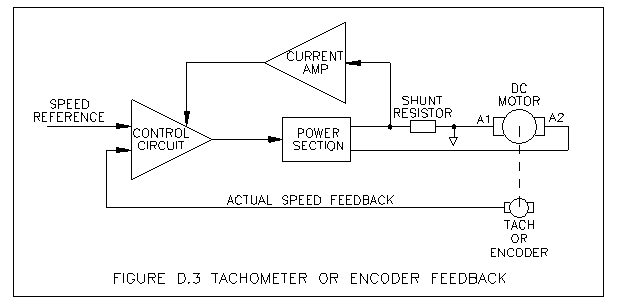
3. EFB — Encoder Feedback
Encoders come in an even larger variety of ratings and output a signal that increases in frequency with speed increases. They can be specified with multiple outputs called quadrature outputs and marker pulses, which permit them to feed back direction-of-rotation and rotational position information.
Some encoders are referred to as pulse tachs or pulse generators. These are usually ring and gear or Hall effect sensor and magnet wheel arrangements that mount to a “C” face or flange on the motor. All encoders are specified in pulses-per-revolution (PPR) and may have output ratings from 1 PPR to thousands of PPR.
Tachometers and encoders include ratings for output accuracy or tolerance, supply requirements, temperature range and load range. Their main claim to fame is that they ignore most external influences and give an accurate and repeatable output as long as they operate within their defined ratings. This means that drives using them for feedback also can ignore or compensate for factors including motor losses, line voltage fluctuation, load change and temperature change.
Here are a few products that support EFB methods:
- TCF60 & TCF120 Series Pulse Tachs: Our Hall effect pulse tachometer ring kits generate digital pulse trains of .60 PPR or 120 PPR and mount on standard NEMA C-face motors.
- TAC008-000 XPY Flange Encoder: For a 300 PPR solution, we offer the TAC008-000 Optical Encoder.
- TAC017-000 Quadrature Ring Encoder: This high-resolution C-face encoder reaches 1,024 PPR and features a rugged build.
AC Drives Velocity Control:
AC Inverter drives can have several selectable control methods. Some examples are:
- V/F control: Also called volts-per-hertz control, V/F control is the most common inverter control method. Requiring no feedback device, it is suitable for general purpose and multiple motor applications.
- V/F control with PG or tachometer feedback: V/F control with PG feedback provides a closed-loop system’s improved speed regulation.
- Open-loop vector: Open-loop vector, sometimes called sensorless vector, utilizes a more complex control algorithm to give precision speed control, quick response and higher torque at low speed.
- Closed-loop or flux vector: Flux vector or closed-loop vector control requires encoder feedback and gives precise speed and full-rated torque control over a wide speed range, sometimes even at zero RPM.
Inverters and their motors can also be operated in a constant horsepower profile where motor speed can be extended beyond the base speed rating with torque capacity de-rating. Refer to Section H.12, “Constant Horsepower Winders” for a more detailed description of this type of operation.
Regeneration:
Regeneration relies on the ability of both AC and DC motors to act as generators as well as motors. Regeneration is an operating mode automatically implemented by a REGEN drive’s velocity control section whenever the velocity feedback exceeds the velocity reference. With regenerative drive capacity, a motor can provide motoring (positive) torque or braking (negative) torque, usually in either direction of rotation. This is called four-quadrant operation. Non-regenerative drives provide only single-quadrant operation, although the addition of reversing contactors with DC drives can allow motoring operation in the third quadrant.
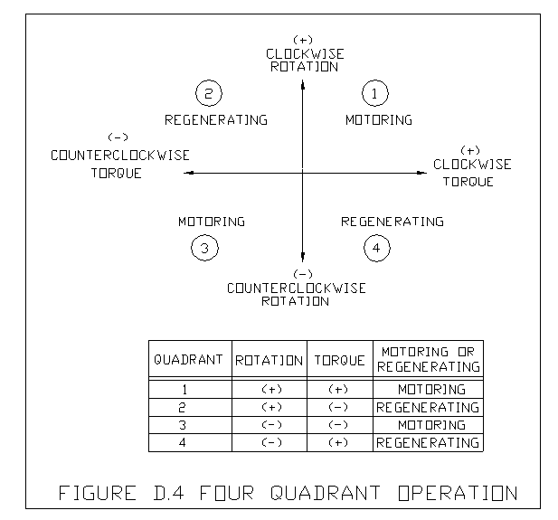
With motoring operation, power is taken from the AC line and converted to produce work by the motor. With regen operation, self-generated power is taken from the motor and fed back to the AC line or energy-dissipating brake resistors to produce negative or braking AC or DC motor torque.
This function is useful when dealing with high inertia or overhauling motor loads. With DC drives, regenerative capability also provides solid-state reversing. Without regeneration, DC-rated contactors must be used for reversing. Even at low load levels, frequent reversing can cause short mechanical life expectancy on contactors. With a regen drive, only a single contactor is recommended for fail-safe stopping.
Regen capability in a DC drive requires a second power section and more control circuitry than in a non-regen type, while most AC inverter drives inherently include some regeneration capability. Most lower-HP-rated AC drives also come with the braking transistor circuitry required for expanding regen capability with the addition of only the braking resistor. Additionally, some AC drives may include line regen capability, where the excess motor energy is fed back into the line instead of dissipating across resistors.
DC regenerative drives typically deliver higher continuous negative torque than inverter drives using a braking resistor. The inverter braking transistor and resistor continuous wattage ratings will determine the operating duty cycle.
Some of our products that support regenerative control include:
- D10425-XXX Series: This regenerative DC motor control offers four-quadrant range for 1/8-2HP motors.
- Trooper® IV: The industrial Trooper® IV Series has full-range speed control for 1/8-2HP motors.
- RCP200 Series: This regenerative control package, designed for performance and versatility, offers full-wave support for 1/4-5HP motors.
- BLAZER® IV Series: As another full-wave regenerative motor control package, the BLAZER® IV Series supports 1/4-5HP motors with a range of high-performing features.
- ELITE® PRO Series (EPR models): The EPR models from the ELITE® PRO Series are second-generation models with regenerative capabilities.
- ELITE® Series (E12 models): The E12 models of our ELITE® Series motor controls are compact panel-mounted assemblies that cover 5-300HP motors.
Discuss Your Motor Needs With Carotron
Whichever motor control method you choose, you’ll need high-quality, dependable components. At Carotron, our experienced engineers apply thorough testing and performance-focused design to every motor control product we create. We can even work with you to build something for your system’s unique specifications.
Whether you know exactly what you need or have some questions, the experts at Carotron can help. Reach out today to learn more!
*Topics in this motor control basics guide include: dc motors torque, ac motor torque, AC motor speed control, and DC motor velocity controller. Read other useful motor control tutorials and application tips by clicking on “Back to Index” below.
Previous “Variable Speed Drive Types” • Back To Index • Next “Multiple Drives – Coordinated Control”
Go to Product Line • Go to DC Drives and Accessories • Go to System Interface Components