CSAG Drive Operating Modes – Motor Control Basics
March 26, 2010
Dancer Control Systems: A Look at Dancer Positioning and Compensation
March 26, 2010| Control Systems Application Guide |
Previous “Drive Operating Modes” • Back To Index • Next “Dancer Compensation”
Multi-Motor Drive Speed & Coordinated Control
There are several methods for controlling multiple motor drives and each has inherent advantages and disadvantages. A primary determining factor for selection concerns whether we’re dealing with a continuous web or length of product as opposed to individual or “parallel” processes occurring at the same time.
Our discussion will address several methods of coordinated control for multiple motor drives:
1.) Basic Follower
2.) Cascaded Follower
3.) Frequency Follower
4.) Follower Mode Negatives
5.) PID Control
6.) Process Control Interface
7.) Transmitter/Receiver
8.) Master Reference (Parallel) Control
9.) Inverted Logic Follower
1.) Basic Follower:
A Leader/Follower scheme remains one of the most cost effective and adaptable methods for coordinated control of two or more motor drives in a continuous web operation. Carotron’s System Interface Design function products include input capability for Frequency, Voltage and Process Current signals and all provide external TRIM pot connections and TRIM RANGE setting adjustments.
A two drive Leader/Follower system is the simplest form of follower implementation. By using a tachometer or similar device mounted on the leader motor or machine section to supply the speed reference to a follower drive, any changes in the leader speed will be reflected in the follower drive.
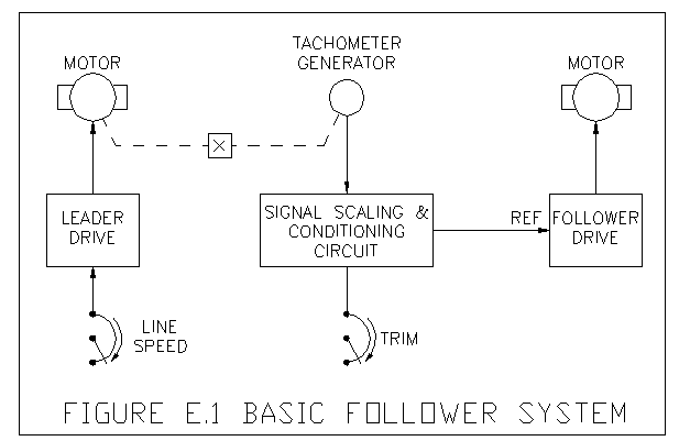
APPLICABLE PRODUCTS:
C10032-000 SIGNAL FOLLOWER CARD
D10562-000 BIPOLAR ISOLATION/LOADCELL AMPLIFIER
SIM200-000 SIGNAL ISOLATION MODULE
2.) Cascaded Follower:
The Basic Follower described above can be expanded with a cascade or “daisy chain” connection to a third drive following the second and so on to allow speed changes to be reflected throughout a process.
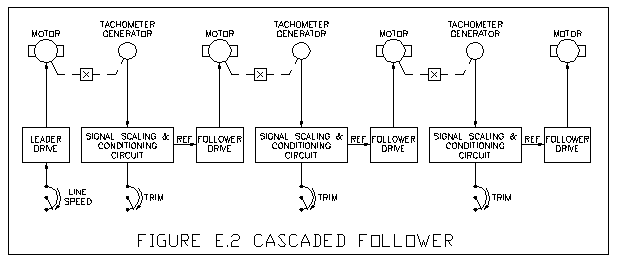
This cascading effect is especially beneficial when three or more drive sections are connected. Here a separate web tension zone is established between any two adjacent driven sections. The ratio of speed between the leader and follower controls the tension level in this zone. If the #2 drive’s following speed ratio is changed or trimmed to adjust the tension level between #1 and #2, the #3 drive will follow the change and the tension level in the zone between #2 and #3 will not be changed. In other words, the cascading effect allows changes to be reflected “downstream” in the web path without the need to correct all follower drive trim ratios.
APPLICABLE PRODUCTS:
C10032-000 SIGNAL FOLLOWER CARD
D10562-000 BIPOLAR ISOLATION/LOADCELL AMPLIFIER
SIM200-000 SIGNAL ISOLATION MODULE
3.) Frequency Follower:
As mentioned previously, with some motor drives, encoders or pulse tachometers can be used in place of DC tachometers. With some “tachometer feedback only” drive models, one of Carotron’s Frequency to Voltage converter cards can convert frequency signals to analog voltages suitable for tachometer feedback control and/or speed reference in motor control systems.
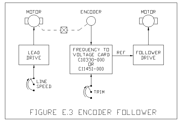
APPLICABLE PRODUCTS:
C10330-000 FREQUENCY TO VOLTAGE CONVERTER
C11451-000 FREQUENCY TO VOLTAGE CONVERTER
FTV220-000 FREQUENCY-TO-VOLTAGE CONVERTER
4.) Follower Mode Negatives:
There are a couple of “negatives” related to follower applications.
First, because any regulation errors by individual drives would be cumulative, multiple steps of cascading may produce more accumulated error than the process can tolerate. For example; in the three drive system described above, assume 0.5% regulation error in the two follower drives for a 1% total system error.
Secondly, all follower drives will experience a finite start-up delay. The leader drive will always have a “head start” since it must start its motor into rotation before the follower drive sees, recognizes and responds to a speed reference. This delay can be minimized with careful set-up but never completely eliminated.
These problems can be further minimized by using the “follower tach or encoder” as actual motor speed feedback for its respective “leader” drive as shown in Figure E.4. Another enhancement would couple the TRIM pots to dancer mechanisms. Refer to Section F. on Dancer Compensation.
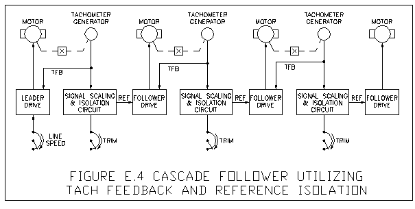
When a tachometer or encoder on each drive is used for both Feedback to the leader drive and Reference to the follower drive, an ISOLATION function may be required to maintain isolation between each section. Refer to Section B for discussion about Isolation.
Cascaded followers require careful set-up. For best results, limit the range of the TRIM functions for either dancer or operator control to the minimum acceptable percentage effect. This is easily adjusted by a TRIM RANGE setting on many CAROTRON interface products and will aid setup and add to system stability.
APPLICABLE PRODUCTS:
D10562-000 BIPOLAR ISOLATION/LOADCELL AMPLIFIER
SIM200-000 SIGNAL ISOLATION MODULE
5.) PID Control
PID control is a closed loop control technique that uses a signal or value of SETPOINT that defines a desired operating level and compares it to a signal or value of FEEDBACK that indicates the actual operating level. The setpoint can represent a desired dancer operating position, a tension level, a load level or a myriad of process conditions that must be precisely controlled. The feedback usually originates from a specialized sensor such as a dancer pot, load cell, current shunt or other device that indicates a real-time value of the controlled condition.
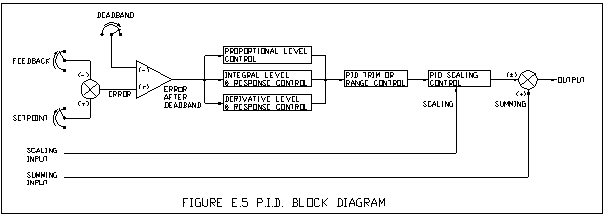
The PID control’s primary function is to provide an output correcting signal or value that minimizes the error or difference between the SETPOINT and FEEDBACK. The expression PID is derived from Proportional, Integral and Derivative processing of the error signal. The presence, polarity, amplitude and rate of change of the error signal initiate and direct the processing techniques. The polarity is determined by the greater of the setpoint or feedback values and determines whether the corrections are increasing or decreasing or adding or subtracting signals.
In Carotron products, the three correction signals are independently adjusted and then are summed together, sometimes with other signals, to produce a complete control signal. In set-up these signals should be initially implemented and adjusted in the “P.I.D.” order with Proportional first, Integral second and Derivative last if at all.
Proportional Processing
Proportional correction is produced immediately from the presence and polarity of an error signal. The level of the correction is based on an adjustable value of gain. Most basic signal conditioning circuits provide outputs that are proportional to their inputs.
Integral Processing
The Integral correction signal is also based on the presence and polarity of the error signal. Depending on the product, it uses an adjustable rate or time of response to produce a signal that will continually increase or decrease (based on the polarity) until the error returns to a minimum level. The integral signal will then “hold” at this level as long as the error remains at minimum. It is the only of the three signals present when there is no longer any error.
The change in level is usually produced at a linear rate which provides a predictable and stable response in most process control applications. Some Carotron PID control products offer a second mode of integral correction where the rate of change is dependent on the amount of error (the greater the error, the faster the integration rate).
Our PID products also include a Deadband adjustment that sets a + “null level” of error that must be exceeded before the Integrator will respond. This is helpful for stabilizing operation in applications that are handling out-of-round material rolls or bent transport rolls.
Derivative Processing
The amount of Derivative correction is based on the rate of change of the error signal. A faster rate of change will produce a greater correction. It is produced only while the error is changing. Care should be used in implementing Derivative correction because its affect can change with large changes in the dynamics of an application such as with a large diameter and mass change on a center driven roll.
All Carotron PID function controls include some unique functions utilizing SCALING INPUT and SUMMING INPUT. These inputs provide ease in combining an optimized PID correction signal with a primary reference signal and even ranging the effect of the correction by the primary reference. For example: a dancer position correction may be scaled to provide + 10% speed trim when a line is operated at 100% speed but, when the line runs at 10% speed, the same dancer trim equates to 100% trim! In other words, the dancer trim range % (and sensitivity) increases as line speed decreases. This can mean different dancer response and stability at different line speeds. Use of the SCALINGSET speed is maintained. function will range the correction signal so that a constant percentage of
APPLICABLE PRODUCTS:
CLT2000-000 CORTEX LT CONTROLLER
D10541-000 DANCER POSITION/PID CARD
MM3000-PID MICROMANAGER PID CONTROL
6.) Process Control Interface:
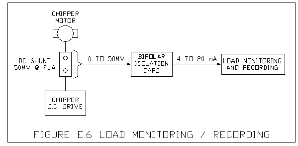
Most applications involving “process control” utilize sensing and monitoring of specific aspects of the process or end product. In many cases the sensors used provide output in the form of low level millivolt or milliampere signals which will normally require conversion, amplification, scaling and isolation to a level that is practical for use by a drive or control circuit.
Devices such as current shunts typically supply only +50 or +100 millivolts full scale output but may be at hundreds of volts potential to ground or to un-isolated circuit inputs. Load cells or tension transducers are also low output devices commonly used in process control.
In some cases sensors already supply a “process output” signal such as 4 – 20 milliamps for full range output but, the actual operating range is only a fraction of the sensor range. For example; a 1000 pound scale may be used to weigh product no greater than 500 pounds so we only see 12 milliamps maximum.
Carotron offers products providing these input/output capabilities, isolation and bi-polar signal processing. For example, the Model D10562-000, Bipolar Isolation Card, can accept any of the Input signals and can generate any of the Output signals listed below.
| Typical Input Signals: | Typical Output Signals: | |
| 0 – 5 mA |
0 – 5 mA |
|
| 1 – 5 mA |
1 – 5 mA |
|
| 0 – 20 mA | 0 – 20 mA | |
| 4 – 20 mA |
4 – 20 mA |
|
| 0 – +50 mV |
0 – +10 VDC | |
| 0 – +100 mV | +10 – 0 VDC | |
| 0 – +10 VDC | -10 VDC – +10 VDC | |
| 0 – +25 VDC | ||
| 0 – +100 VDC | ||
| 0 – +200 VDC | ||
| 0 – +250 VDC |
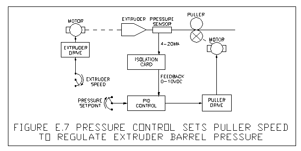
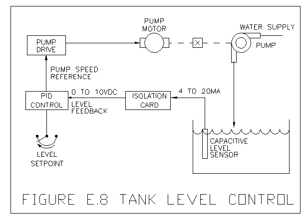
Since the output of these circuits is proportional to the input, they can sometimes be used as simple controls where a direct action proportional to the input must take place. Quite often their outputs are used as the feedback to a PID controller to give precise control of the process variable being sensed. Refer to Section E.5 on PID Control. Some examples follow:
APPLICABLE PRODUCTS:
LCA210-000 LOAD CELL AMPLIFIER MODULE
SIM200-000 SIGNAL ISOLATION MODULE
7.) Transmitter/Receiver Control:
A very specialized form of follower is the Transmitter/Receiver configuration shown in Figure E.9.
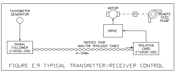
This scheme can be used to follow or allow control by a low level voltage signal whose source is too remote to allow the use of a standard voltage follower. Typically, voltage signals are fed into high input impedance circuits to prevent excess loading and distortion of the signal. When long wire runs are used to carry these signals, several problems can occur.
1. The long lead wire can act as an antenna which picks up or receives radiated RF or transient energy.
2. The resistance of the lead wire can cause voltage drops in the transmitted signal that distort or alter its true character.
3. The capacitance of the lead wire can cause signal delays or filtering action that distort or alter signal character.
By converting the voltage signal to a process signal of 4 to 20 mA, the reference can be transmitted over much longer distances through twisted pair cable and be converted back to isolated voltage at the receiving end. By transmitting the signal as a higher power “process current” level, the effects mentioned above can be minimized or eliminated.
APPLICABLE PRODUCTS:
C10032-000 SIGNAL FOLLOWER CARD
SIM200-000 SIGNAL ISOLATION MODULE
8.) Master Reference (Parallel Control):
In a Master Reference application, a primary control signal such as a master pot., tachometer, process signal or frequency signal is used to control the speed of two or more motors. The start-up delays associated with the cascade follower systems are effectively eliminated since the individual motor drives receive start-up commands and reference signals at the same time while remaining electrically isolated from each other and the source of reference.
Master Reference control is also appropriate for non-web applications such as metering pumps or feeder controls where precise mix percentages must be adjustable and maintained over the system speed range. Figure E.10 illustrates shows the Master Reference control being used to regulate speed and mix ratios for the contents of asphalt in a hot mix plant application. Here the manually set speed ratios are maintained over the plant operating speed range.
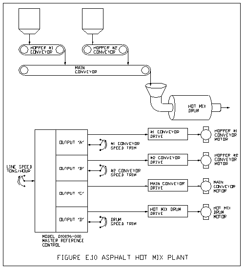
Also included are acceleration and deceleration adjustments for use with a master potentiometer input. Using the master ramp function is very desirable to produce orderly start and ramp-to-stop functions by controlling the acceleration and deceleration time required by the system. Without this feature it would be necessary to match the acceleration and deceleration rates of the individual drives which can be difficult.
One shortcoming of the MASTER REFERENCE control scheme for continuous web applications is that any speed trim initiated for individual drives and any speed change due to load will not be automatically reflected in other “down-stream” drives of the process.
When handling a continuous web, the MASTER configuration is best applied in applications where one of the following situations exists.
1. With no other method of compensation; the material being processed must be of sufficient strength that it can withstand considerable tension due to regulation differences between the individual drives.
2. The objective of the control is in fact pure velocity control of the individual motors and the web is expected to be affected by the differences – such as in progressive draw applications.
APPLICABLE PRODUCTS:
D10096-000 MASTER REFERENCE UNIT
SIM200-000 SIGNAL ISOLATION MODULE
C10209-000 SIGNAL ISOLATION CARD MODULE
9.) Inverted Logic Follower:
A few applications call for inverted logic. Most signal conditioning circuits will give an increasing output with an increasing input. Inverted logic will give a decreasing output with increasing input. This capability is available in several standard Carotron products as an optional calibration set-up. It is generally used as a very simple “proportional” control method for non-critical applications.
For Example: A drive used for a pump control or feeder control can be set to operate at a maximum speed with light load or pressure. An increasing signal from a load sensor or pressure transducer, etc. can cause a proportional decrease in motor speed until a balance is achieved – within the defined operating range.
APPLICABLE PRODUCTS:
C10032-000 SIGNAL FOLLOWER CARD
*Topics in this guide about controlling multiple motor drives include: follower circuits, PID control, process control interface, master reference control, follower mode negatives, and more. Read other useful motor control tutorials and application tips by clicking on “Back to Index” below.
Previous “Drive Operating Modes” • Back To Index • Next “Dancer Compensation”
Go to Product Line • Go to DC Drives and Accessories • Go to System Interface Components
